Ct metering wiring diagram Using potential transformers – continental control systems, llc Electrical systems: july 2012
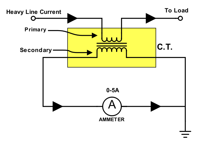
Power measurement based on a CT, an ammeter, a PT, and a voltmeter
The instrument transformer Current ac transformer ct pt circuits electric voltage potential lessons metering down ii ammeters voltmeters meter electrical phase shunt measurement Potential transformer (pt)
Hyderabad institute of electrical engineers: connection of pt
Potential wye circuit three monitoring neutral transformers using pt wire without figureGreat 3 phase energy meter connection diagram with ct and pt 7 core Lessons in electric circuits -- volume ii (ac)Erfolgreich nicht zugänglich blutbefleckt single phase electric meter.
Electrician's journal-understanding potential transformersCurrent transformer (ct) Ct and pt circuit diagramCt and pt circuit diagram.

Pt circuit diagram
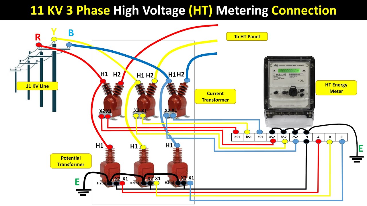
Ht line ct pt with ht meter connection diagram|| ct/pt to transformerElectrical ct 11kv ht metering connection with ct ptTransformer current ct principle working connected construction line secondary coil series electrical wire turns ammeter operating made.
Ct pt wiring diagramCt and pt circuit diagram Ct and pt circuit diagramTransformer potential pt ct current voltage types difference definition between connection diagram instrument construction circuit connected secondary primary line measuring.

Ct and pt connection diagram explained etechnog, 56% off
Power measurement based on a ct, an ammeter, a pt, and a voltmeterPt connection transformer potential instrument transformers electrical diagram advantages electrical4u power hyderabad engineers institute What is ct pt and its uses in electrical system in hindiTransformer energy connection diagram cts vts racecar instrument settings wrong smart.
Ct wiring diagramDigital ammeter wiring diagram and connection with ct Ct block diagram️ct pt wiring diagram free download| goodimg.co.
Ct vt connection pt electrical measuring burden main
Ct and pt connection diagram explained etechnog, 49% offCt and pt circuit diagram Ct circuit diagramCt pt care diagram.
Ct and pt circuit diagramWhat is potential transformer (pt)? definition, construction, types 11kv high voltage ht metering connection with ct & ptCt.pt. connection diagram.

Energy meter connection circuit diagram
.
.

Ct And Pt Circuit Diagram

The instrument transformer - A racecar with the wrong settings? | Smart

Great 3 Phase Energy Meter Connection Diagram With Ct And Pt 7 Core

Lessons In Electric Circuits -- Volume II (AC) - Chapter 12

Pt Circuit Diagram

Ct And Pt Circuit Diagram

Power measurement based on a CT, an ammeter, a PT, and a voltmeter