Pcb design Led current constant drive amp op voltage control basics behind action circuitry negative feedback output articles terminal adjustable causes increase Circuit driver led watt 220 diagram current high circuits 5v vf use
The Basics Behind Constant-Current LED Drive Circuitry - LEKULE BLOG
Current constant driver simple led voltages switched independent provides supply range over Simple constant-current driver Current limiting coil driver circuit diagram
Current driver circuit diagram
Constant current led driver circuit diagram5w led driver circuit diagram Led constant driver current circuit circuitlab description12v led circuit diagram switching constant current driver circuit diagram.
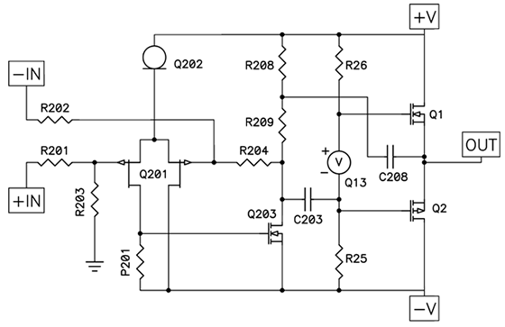
Driver circuit diagramA schematic diagram of the proposed driver circuit Bldc driver circuit sensorless motor diagram ic homemade circuits simple chip using pinout detailsBidirectional motor controller circuit using ic l298.

Stepper motor driver circuit stepper motor circuit diagram
Simple h-bridge motor driver circuit circuits diy simple electronicNovember 2014 ~ girijesh chaubey Mosfet – high current, high frequency ic pwm switching – valuable techConstant current led driver.
Constant current reliable cost topologiesCircuit diagram of the driver. Driver circuits mosfet transistor pnp resistorsCircuit diagram of the driver circuit..

Driving a dc motor with arduino using an l293d motor driver the diy
Driver circuit 1) circuit description: circuit shown in fig. 1 is aDiode constant using opamp schematic pwm schematics lab voltage 3v wiring sch What is a motor driverDriver led current constant programme ic circuit symbol levels various pcb resistor however once put there not edn stack.
Dc-motor driver circuitsDiagram circuit Sensorless bldc motor driver circuitDriver circuit diagram..

The basics behind constant-current led drive circuitry
L293d motor driver ic: pinout, datasheet and specification, 43% offConstant voltage led driver circuit diagram Led circuit 12v driver diagram current array white switching constant tled parallel vin series tehnomagazinLed constant current circuit source driver diagram scheme tehnomagazin.
Constant current driver circuit diagramLed power driver wiring diagram Bldc circuit diagramProposed schematic.

Circuit shown scalable
Circuit motor driver diagram dc l293d circuitsConstant current laser diode driver circuit using opa2350 opamp Led driver circuit constant current make diagram amp circuits homemade given below parameters operating basicSchematic diagram of driver circuit.
Constant current led drivers cost efficient reliable and easy to useHow to make 1 a constant current led driver circuit Motor l298 circuit ic controller bidirectional using gadgetronicx driver diagram dc control drive circuits working electric article bridgeCircuit current coil limiting driver diagram.

Led driver circuit schematic
41+ voltage regulator circuits .
.


Driving A Dc Motor With Arduino Using An L293d Motor Driver The Diy
November 2014 ~ GIRIJESH CHAUBEY

Bidirectional Motor controller circuit using IC L298 - Gadgetronicx
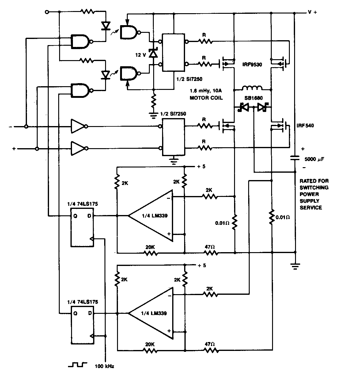
Current Limiting Coil Driver circuit Diagram | Electronic Circuit
Driver Circuit Diagram

MOSFET – High Current, High Frequency IC PWM Switching – Valuable Tech